

Blog Post | Drive Your Reality/HD Animations with Virtual CRASH 3 | Part 1
Are you a die-hard fan of FARO (formerly ARAS) Reality or FARO HD, but wish there was a way to create your animations using a true 3D physics simulation tool like Virtual CRASH 3? If so, this post is for you. Here we demonstrate just how easy it is to extract the 3D simulation data from Virtual CRASH 3 and use it to define an animation path within FARO Reality.
If you're a fan of Virtual CRASH, then you've probably seen this amazing promotional video by now:
The 3D terrain model for this scene was created in Pix 4D software starting from a drone scan of the accident scene. A 3D mesh was generated in Pix 4D, and exported in dxf format and imported into Virtual CRASH 3. A top-down orthographic image was generated for the scene, which serves as the color map for the terrain mesh in Virtual CRASH (using the "receive projection" option).
Pix 4D can also export point clouds of the scene, which can be directly imported into FARO Reality and HD. The source of the point cloud is irrelevant, as this file could also have been generated by a 3D scanner. Here we see our point cloud file in FARO Reality.
Now we need our simulation data from Virtual CRASH 3 in order to be used as a motion path in the FARO Reality animation. Simply create a dynamics report by pressing the "create" button in the "report dynamics" menu in the left-side control panel:
We need to modify the Virtual CRASH data in order to be compatible with FARO Reality, so we first need to paste it into a spreadsheet application:
In the report above, angle - X is roll, angle - Y is pitch, and angle - Z is yaw.
The expected file format in both FARO Reality and FARO HD are:
time (seconds), x (ft), y (ft), z (ft), roll (degrees), pitch (degrees), yaw (degrees), Vx, Vy, Vz
Vx, Vy, and Vz are not actually used, so they can be set to 0.
There is also header data that is expect in the form:
1 MAKE : Name
t[s] x [ft] y [ft] z [ft] phi1[deg] phi2[deg] phi3[deg] vx[mph] vy[mph] vz[mph]
where phi1 is roll, phi2 is pitch, and phi3 is yaw.
It is often easiest to start from a blank template file. You can find our Template.txt file here. We find it easiest to paste data into this template file, creating one file for each vehicle. We will return to this file after we do some data additional data formatting.
We now need to do a little extra work to format our data for use in FARO Reality and FARO HD. This is because these products use a reference point at z = ground level rather than the exact CG position as most simulators use. For collisions where there isn't a lot of pitch and roll to worry about, this isn't necessarily a problem, but when there's significant pitch and roll, we must correct for it (see Part 2 to read more about cases involving minimal pitch and roll).
If we do not correct for this, we will see our vehicle roll beneath the ground:
In this image, we see the yellow vehicle using uncorrected animation path data, and the green vehicle is using corrected data. The yellow vehicle appears beneath the ground because the reference point, which sits at z=0 in the vehicle local frame, is at CG height in the Earth frame.
We need to shift our reference position from the vehicle CG to (xCG, yCG, z = 0), but this isn't trivial since as the z position will change as our vehicle's orientation dynamically changes. What we need to do is to first define a vector in vehicle space that points down to the Reality/HD reference point, and then rotated it based on the vehicle's yaw, pitch, and roll. To simplify matters here, we're going to just assume that the Reality/HD reference point's x and y positions are approximately sitting at the cg location in the vehicle's local x-y plane. In the Virtual CRASH 3 simulation, the vehicle's cg height was set to z = 1.772 ft. So, first we start by defining the local z-axis vector in vehicle space:

Next, we need to define the vector in vehicle space that points straight "down" the local z-axis from the CG to the ground plane:

where h_cg is the "c.g. height" parameter for your Virtual CRASH vehicle.
So, now we have the definition of the vector pointing from vehicle CG to the reference point used in Reality/HD. Finally, we need to define the rotation matrix that takes us from vehicle frame to Earth frame. Recall from the Appendix 3 of the User's Guide, that we can transform any vector, v_{Earth}, from Earth frame and vehicle frame by use of the rotation matrices:
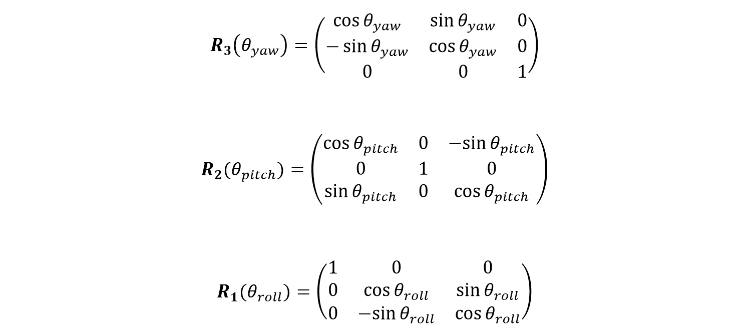
which are applied sequentially by:

The inverse of each rotation matrix is simply given by:

The inverse transformation therefore, which takes any vector, \(v_{Vehicle}\), from vehicle frame to Earth frame, is given by:

where the inverse transformations are applied in reverse order. From this, it is obvious we have:

thus satisfying the definition of an inverse matrix, where I is the identity matrix.
Finally, what we are after is the earth frame definition of the vector which points straight "down" from the CG in the vehicle frame. This is given by:

or, after performing the matrix algebra:

We now have the vector which points from vehicle CG to the point of reference used in Reality/HD. All that is needed now is to add this vector to the vector pointing to the CG position versus time in Earth frame. .
Now, take your spreadsheet application, and reformat your data from Virtual CRASH as shown here:
It is often easier to pre-calculate your trigonometric functions:
Next, calculate the vehicle's local frame z-axis orientation in Earth frame using the equation above for vector v. We also included a cross check for the rotated vector's magnitude, which should always equal 1:
Now, calculate the reference point position vector's components in Earth frame (remember the reference point approximately sits beneath the CG on the ground plane):
Finally, simply add these x, y, and z reference vector components to the CGx,y,z position data from your Virtual CRASH report. This will give you the Reality/HD reference position in Earth frame:
Now, copy the data (without the header):
Paste the data into your Template.txt file:
Don't delete the footer data with spaces at the bottom:
In FARO Reality (or HD), use the "Load Animation Path from File" option, and select your data file.
You're done! You're now animating in FARO Reality (HD) using data from the Virtual CRASH 3 physics model!