
Blog | Importing Scenes from IMS Map360
Importing diagrams created with IMS Map360 is easy in Virtual CRASH 4. In this post we'll show the typical workflow to export a line drawing and point cloud from IMS Map360 to Virtual CRASH 4. Our final objective is to simulate the following on top of a terrain mesh constructed from our point cloud data:
In this scenario, a blue Chevrolet Camero and red Volvo 900 series are involved in a t-bone collision.
The Camero's pre-impact travel path is approximately 38.6 m long. The Camero travels at a constant 60 kph for 1.2 seconds over 20 m then decelerates at 0.7 g's over the remaining 18.6 m to an impact speed of 17 kph.
The Volvo's travel path is approximately 12.6 m long. The Volvo accelerates at a rate of 0.3 g's from a stop to a final speed of 31 kph.
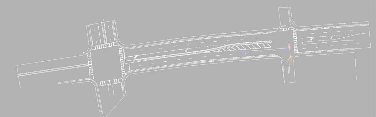
Here we see our line drawing in the IMS Map360 application.
Here we export the CAD diagram in dxf format. Then we drag and drop your dxf file into the Virtual CRASH 4 environment or use Project > Import. Dxf line drawings can be imported using the “mesh” option.
Currently, dxf files are imported as monochromatic objects. To change the color of the lines, simply use the color drop down menu in the “misc” menu in the left-side control panel.
Next, we import our point cloud data. Using the translation grips, we carefully re-position our line drawing such that it’s aligned with the corresponding features observed in the point cloud. In this case, we want to match the striping. Note, we also elevated our line drawing so that it floats above the point cloud. This way we can see our vehicle depicted vehicle positions as we work on our simulation project. This is shown in the video below:
Next, using the Easy Surface Builder tool, we’ll create our surface mesh for our terrain. Note, we will not remove points at this step, as we’ll come back and clean up our scene after we create our mesh.
Now, again using the Easy Surface Builder tool, we go segment by segment, remeshing our point cloud, but with the remove points feature enabled. This will allow us to carefully remove points we don’t want visible above our road surface.
Finally, we bring in our vehicles. In the video below, we set up our vehicles on top of the terrain mesh created with the Easy Surface Builder. The mesh was converted to a terrain object so that the Virtual CRASH physics simulation engine allows the vehicle objects to interact with the terrain in 3D. Using the interactive feedback from the simulation engine, we were able to quickly converge upon a simulation solution for our scenario. The optimization process is shown below.
Below we see the final animation.
Simulating over point cloud rather than surface mesh
Occasionally, one may wish to visualize vehicles moving over point clouds rather than the Easy Surface Builder polygon mesh. Using the section tool, we can reload all of our point cloud points into view.
Hiding the terrain mesh from view, we now achieve the illusion that our vehicles are moving directly on top of the point cloud data. Here, we’ve insert a black filled polygon on the x-y plane for a better visual effect.
Below we see the final animation with hidden terrain surface.