Building Complex Systems with Joint Tools
Updated on November 7, 2018.
Joints are covered in a few different places. For example:
User’s Guide (VC5 | VC4 | VC3)
http://www.vcrashusa.com/blog/2016/7/3/making-rotating-assemblies-with-a-hinge-joint

Virtual CRASH includes a number of joints which can be used to connect rigid body objects together in various ways. You can even make joints articulate. Joints can be used in a number of ways, from creating a simulation of a broken streetlamp post to simulating a rollover accident. In this blog post we review the various joint types. To access the joints, simply go to the Create > Physics menu, or use the toolbar shown below.

In order to create a joint, you’ll first need some rigid body objects in your scene. Here we’ve made an ellipsoid and a box. It's best to learn how to use joints with simple systems involving primitive shapes before moving to more complex systems such as 3D models of heavy machinery.
Here, we’ve made the ellipsoid a rigid body by using Create > Physics > Make Rigid Body from Selection. We made the box an immovable object by using Create > Physics > Make Unyielding / Terrain from Selection. We changed the ellipsoid’s weight to 100 lbs. We’ve started the ellipsoid above the box, which means it naturally wants to fall downward.
The Hinge Joint
Let’s now experiment with the hinge joint. This is the easiest joint to understand. It has one rotational degree of freedom about its rotation single rotation axis. To create a hinge joint, simply select the hinge joint icon from the dropdown menu.

Next, hover your mouse over the first object you wish to connect to the hinge joint. In this case we’ll use the box. You’ll see the object turn light blue, indicating it is selected. Then left-click and hold the left-mouse button. Next, drag and hover your mouse cursor over the second object you wish to connect, then release the left button. If for some reason, the first object does not turn light blue, you may need to left-click on the first object once, then you should see it turn light blue, then left-click again.
You’ll now see the hinge joint in the scene. Note, its rotational axis is aligned with the global z-axis by default.
Giving the red ellipsoid an initial speed greater than 0, we see it now rotates about the hinge joint axis; however, it abruptly stops after rotating 45 degrees. This is due to the joint limits setting.
By default, the joint starts at a 0 degree articulation angle. After the joint swings through an angle of 45 degrees, it hits the joint limit, after which a damped spring force as applied to return it back to within the range allowed by the “axis1-min” and “axis1-max” settings in the “limits” menu. Note, the strength of the restoring force that keeps the joint within these limits is controlled by the “spring” and “damping” constants in the “limits” menu. The rotations are in standard convention, where positive rotation angle is counter-clockwise about the joint’s z-axis.
As we expand the limits parameters, we see that the ellipsoid is able to rotate further about the joint’s z-axis.
Note, one way to force the ellipsoid to stay at a particular angle is to change the min and max axis1 parameter such that the joint torque forces the ellipsoid to move to within your narrow range at the start of the simulation.
You can learn more about how the spring and damping coefficients work in the limits menu by visiting the Short Glossary page: https://www.vcrashusa.com/short-glossary/.
Unrestricted Rotation
By deselecting the “use” option, we can allow for full unrestricted rotation. This can also be achieved by setting the min and max axis1 values to 0. In the image below, we see the result of removing joint limits. Here we use the show interposition step option to visualize the ellipsoid’s position every 0.25 seconds (set in the ellipsoid’s “interpositions” menu).
Joint Integrity
The joint is held together with a damped spring force. The spring and damping constants can be set in the “joint” menu. Note, if the spring stiffness is sufficiently reduced as shown below, the joint will be pulled apart. In some occasions, depending on the complexity of the system, and the number of joint constraints that need to be simultaneously satisfied, you may need to increase the joint stiffness value beyond the default value to ensure the joint integrity is maintained within a reasonable tolerance for your simulation.
Note, every joint type, including the multibody ragdoll joint, uses a spring constant and damping coefficient.
The spring constant value used internally by the simulation engine is of the form:
$$k_{internal} = {m_{1}+m_{2} \over 1~kg} \cdot k_{user~input}$$
The damping coefficient value used internally by the simulation engine is of the form:
$$b_{internal} = {m_{1}+m_{2} \over 1~kg} \cdot b_{user~input}$$
where \(m_1\) and \(m_2\) are the masses of the connected objects. These conversion helps ensure simulations remain stable for increases in linked object masses.
Note, if one of the connected objects is infinite in mass (using Physics > Make Unyielding / Terrain from Selection), then the internally used spring constant is:
$$k_{internal} = {m \over 1~kg} \cdot k_{user~input}$$
and the internally used damping coefficient is:
$$b_{internal} = {m \over 1~kg} \cdot b_{user~input}$$
where \(m\) is the mass of the finite mass rigid body object.

Specifying Orientation
Another way to specify the orientation, or articulation angle, is to use the “axis1-angle” value in the “fix orientation” menu. Input the desired value and enable the “use” option. Note, after the simulation starts, you’ll notice the hinge joint angle move toward the input value, and oscillate about the desired joint angle, eventually settling to equilibrium about the input value. This motion is controlled by a damped spring torque versus articulation angle, which is controlled by the spring and damping values in the “fix orientation” menu. Note, with damping = 0, you’ll see persistent oscillations about the selected axis1 angle (see below). Note in the figure below, the ellipsoid acceleration reaches 0 as the hinge reaches 45 degrees.
As the damping parameter is increased (for a fixed value of spring constant), critical damping is reached, thus stopping the oscillatory behavior.
You can learn more about how the spring and damping coefficients work in the fix orientation menu by visiting the Short Glossary: https://www.vcrashusa.com/short-glossary/.
Driven Motion
The hinge joint orientation angle can be specified as a function of time by using the diagram tool option. The diagram tool has been introduced in other posts. To select the tool, simply left-click on the box next to “axis1-angle”.
In the case below, we used the “free hand” tool to draw the orientation versus time function. Note, the spring and damping constants were increased to large values to ensure that the joint angle change promptly without significant oscillation as the input driving function changed. Note, in free hand mode, you can insert more segments to define more points in the diagram.
It is a good idea to verify the motion of your objects by either using the diagram tool or the dynamics output. Here, using the diagram tool, we can check that the ellipsoid’s yaw angle as a function of time matches up to our expectation from the input driver function. We see the time-yaw graph below:
The motion is shown below.
Remember, the joints are connecting rigid body objects, which themselves can interact with other objects. Here we show an impact between the ellipsoid, which rotates into the cylinder.
Moving the Joint
You can move the joint by first selecting “Parent Space”.
You can then left-click on the joint and moving it with your mouse or using a Restrict To option to use the translation or rotation grips. Note, rotating the joint in Parent Space mode will note have an effect on the rotation. Translating the joint will, of course, change the point in space about which rotation occurs. Also note, by translating the joint, the orientation of the connected objects will change with respect to the joint axis.
You can also rotate the joint’s orientation using the Parent Space option. Be sure to select a Restrict To option to access the rotation grips.
By using the “Child Space” option rather than “Parent Space”, you can change the initial orientation of the joint away from 0 degrees. Note, however, that changing the joint’s initial orientation does not change the connected objects’ orientations.
Translating a joint in “Child Space” is not advised (except in special situations) since that essentially pulls the joint apart as an initial condition. Thus, when the simulation starts, the restoring force will try to reconnect the joints. It is necessary to translate part of a joint in Child Space. This is discussed below.
Repositioning Connected Objects
As you move your connected objects around the scene, the two halves of the joint will break apart. As the simulation starts, the joint will then try to reconnect the halves. Thus, if you need to reposition your objects after already connecting them, first set their new positions. Then switch to Parent Space and position the first half, then switch to Child Space and reposition the second half so that the two halves start already connected. If you want to remove the combined system, keeping the same relative positioning and orientation of the connected objects, the best way to do this is to simply make a group containing the connected objects and joints. You can then easily translate and rotate the group object.
Making an Articulating Dump Truck
Let’s create an articulating dump truck using two hinge joints. We’ll start with the Mack dumper.
Using the “Elements” selection mode and the lasso tool, lasso the polygons for the bed of the truck. In the faces menu left-click on “detach”. This will create a new object from the polygons of the bed.
Now that your bed is detached, hide it, and look for polygons that are left over, that you may want to delete from view. For example, in the figure below, we’ll select these polygons and delete them.
Unhide your bed object and select it. Still in Elements selection mode, lasso the polygons for the rear tailgate. Again press “detach” in the faces menu. The tailgate will become a separate object.
Switch back to Object selection mode so that you don’t accidentally modify polygons. Now, make both the bed and the tailgate rigid body objects. Set the weight of the truck, bed, and gate as needed for your case.
You’ll need to adjust the CG position for the bed and the tailgate. Simply select the bed, then select the Pivot selection mode. You should then see the CG. Left-click on the CG and move it as needed. Failure to place the CG at a reasonable location could result in unexpected motion.
Use a hinge joint to connect the bottom of the truck to the bottom of the bed at the rear, just under the tailgate. Be careful not to select the tailgate.
You’ll need to switch to “Parent Space” mode to reorient the hinge axis 90 degrees. Switch to one of the Restrict To modes to see the rotation and translation grips. Here we placed the joint at the center of the truck, although this doesn’t really matter since there’s only one degree of freedom.
Now use a hinge joint to connect the tailgate and bed.
Again, you’ll need to rotate it after connecting the objects.
Let’s set the joint limit so that the tailgate can’t swing into the bed. No need to use fix orientation with this joint since we want the tailgate to swing up as the bed tilts back.
Now select the bottom hinge. Disable “use” in the “limits” menu. In the “fix orientation” menu, left-click on the box next to “axis1-angle”. Here we selected the intervals option, since this is a great way to force smooth motion. Using the diagram, we fine-tune the maximum angle and rate. In this case it is necessary to increase the spring and damping rate to large values to ensure the bed moves with the hinge without much lag or oscillation. Also note, for both hinge objects, it is necessary to use the “disable before break” option in the “contact” menu. This ensures that polygons do not interact between objects connected by joints, which can cause snags and other undesirable effects.
We loaded the dump truck with rocks. Finally, we grouped the rocks, joints, truck, bed, and tailgate together as a single group object. This makes it much easier to rotate and translate the truck and payload. Note, if you group together rigid body objects, you will probably want to ensure the "auto align to plane" option is disabled (in the "misc" menu). In this case, the "auto align to plane" option would cause the rocks, tailgate, and bed to automatically snap to the x-y plane as soon as they are translated through the scene, so it was disabled for all objects.
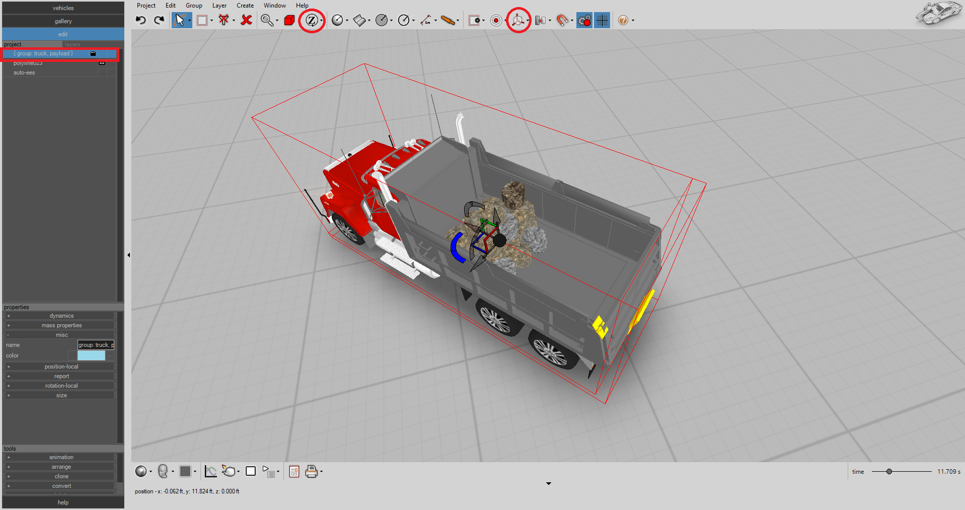

Below we see our final animation.
The Universal Joint – Two Hinge Joints Combined
Universal Joints are ideal for pivot points with two rotational degrees of freedom, such as at the base of a crane:
Now we’ve created a new scene with simple shapes to experiment with the Universal Joint. Again, our blue box is an immovable object and our box is a rigid body. We’ve connected the two with a Universal Joint. The joint has been rotated in a more natural orientation for better ease of use – note, it wasn’t necessary to do this, as the joint limits could have been set to accommodate any joint orientation. Notice now, in the “limits” menu, there are two sets of axis limits. Axis1-min/max correspond to limits for rotation about the joint’s own z-axis. Axis2-min/max correspond to limits for rotation about the joint’s own y-axis. Just like with the hinge joint, limits can be set to restrict the range of motion as needed.
In the video below, we show how the joint articulates as you change the axis1 angle.
Next, we show the combined motion of articulating about both axes.
Finally, we add an extra arm and second Universal Joint. The two-arm system is made to interat with another ojbect in the scene.
Spherical Joint
The Spherical Joint is much like the Universal Joint, in that it allows for two degrees of rotational freedom; however, the spherical joint articulation angles cannot be set. In the figure below, we have box set as a terrain object connected by spherical joint to a rigid body sphere. As soon as they are connected, the sphere becomes falling in a pendulum motion.
Enabling the “fix orientation” option, allows us to maintain the initial orientation of the joint.
This is a quick and easy way to hold two rigid body objects together in your scene. Occasionally, you may need to attach objects by multiple joints to hold them in a fixed relative position.
Like any other joint, the connection can be severed as a function of time, force, or torque threshold.
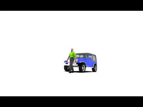
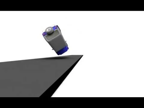
Below we see an example of using two different joints to connect the same two objects. First, the door of the van was detached, made a rigid body, and reattached to the van using the same method demonstrated above for the dump truck using a hinge joint. In order to hold the door closed, we attached the other side of the door to the van using a spherical joint, whose connection was broken during ground contact. The driver multibody object was converted using the convert > to rigid body option. Once this is done, you can then connect the segments of a multibody to any other rigid body object using the joint tools. Here we connected the upper torso to the seatback using a Spherical Joint. The joint connection was broken at 3 seconds into the simulation to allow the body to be ejected from the vehicle. Using this method, one does not need to use the Physics > New Simulation Point (that method was demonstrated in Chapter 15 of the User’s Guide) with Virtual CRASH 4.

Note, another approach we could have implemented is to use only the hinge joint with use “fix orientation” enabled, where the spring and damping constants are held at large values until the door contacted the ground, at which time the constants could be set to zero.
Slider Joint
Slider Joints can be used for modeling hydraulic cylinders such as those used in forklifts, sliding gates, and other mechanical devices. Below we have a scene with the blue box made into a terrain object and the green cylinder a rigid body. They’ve been connected with a slider joint. One thing you’ll likely encounter is that the slider joint will tend to snap closed immediately after simulation. This is because by default the joint limits are small. These are easily adjusted in the “limits” menu. Note, the limits define a window (the blue cylindrical volume) about the start of the joint about which the end point is allowed to occupy (see figure below). As with all joints, you can also disable joint limits by unchecking the use box in the “limits” menu.
Also note, by default the objects can rotated about their start or end connection points as if they’re connected with spherical joints. To prevent this rotation, simply enable use “fix orientation”. You’ll likely need to increase the spring and damping constants.
As with all joints, the axis position can be specified as a function of time using the diagram tool (see video below).
Below is a video demonstrating how to use a slider joint for a forklift.
Here is the corresonding animation:
Car-Wheel Joints
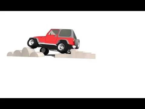
The Car-Wheel Joint is used to mount a rigid body wheel to another object. With this joint, you can also specify its angular velocity or the amount of torque to be applied. The video below shows the process of connecting rigid body wheels to a jeep. Note the wheel objects are 3D polygon mesh objects imported into Virtual CRASH.
Here are the corresponding animations: