
Blog | Summer 2026 Software Update

The Summer 2026 Software Update is here, bringing awesome interface improvements to help you work faster and smarter. The best part? It's completely FREE. No extra license fees, no annual maintenance fees. Read on to see everything this update delivers.
Updates to the Smart Optimizer
Optimizer constraint | “3d” toggle
The Smart Optimizer (learn more) can now use (x,y,z,yaw,pitch,roll) information in the objective function. This toggle is located in the optimizer constraint object's "misc" menu. When disabled, only the x-y projected position is considered, along with yaw (if "use orientation" is enabled). When enabled, the full 3d position is used, along with yaw, pitch, and roll.
Optimizer constraint | “Cumulative orientation” toggle
You can now optimize based on cumulative rotation in yaw, pitch, and roll. This is helpful because you don't need to place intermediate optimizer constraint objects, but only one at the rest position with the desired number of rotations. The cumulative number of rotations is calculated separately for yaw, pitch, and roll, and is defined relative to the vehicle's initial orientation at time = 0 s in the simulation. The normalization factor used in the objective function for the delta-yaw, delta-pitch, and delta-roll terms is 180 degrees. Therefore, when using the "cumulative orientation" option, consider de-weighting the parameter so it doesn't dominate the objective function behavior.
Update to Print Template
“Tabloid” is now available in the paper > size dropdown menu. You can learn more about the Print Template tool here.
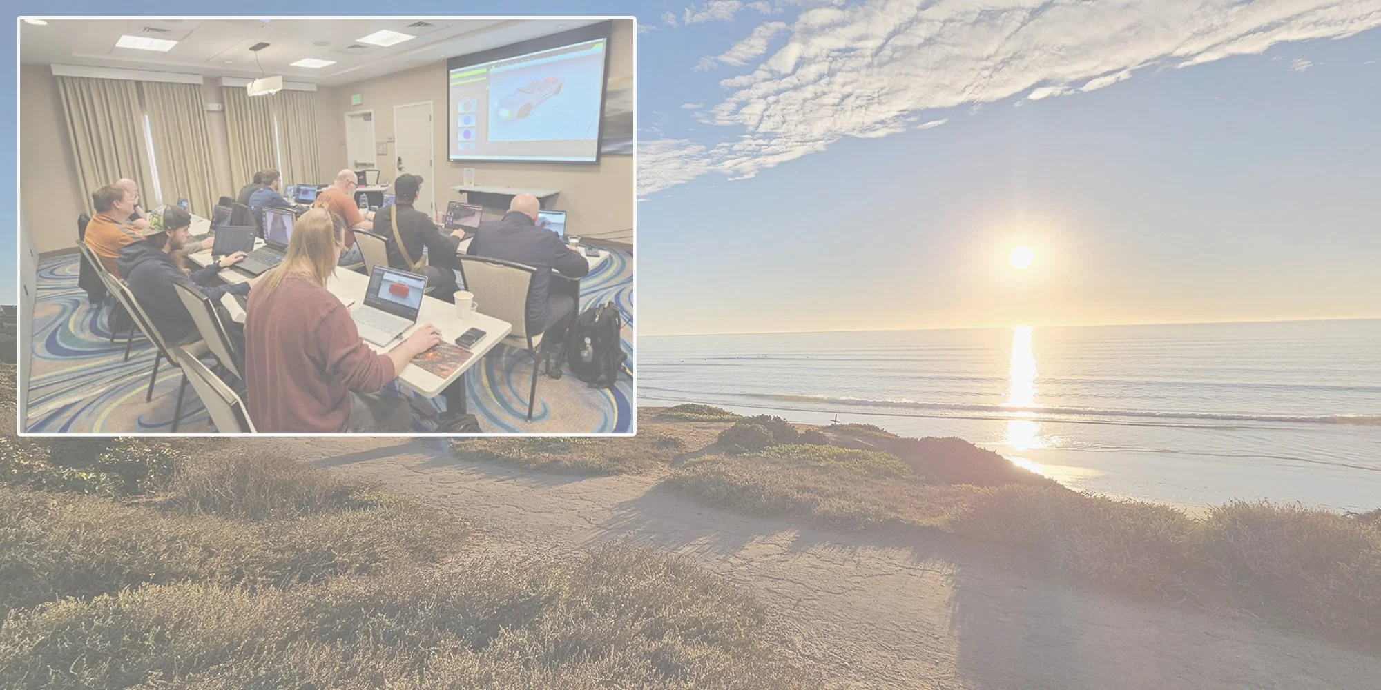
Upcoming in-person training classes

Update to Video Analysis Tool
Dynamically adjust object tracks in 3D space or pixel space
To illustrate, we begin by creating a manual track related to the point of contact between the motorcycle’s front tire and the asphalt (after calibrating our camera).
Switch your cursor control to "Select, Move and Manipulate" [F3], and change your camera's selection type to "Tracks" [Shift+T]. You'll notice the object track switches to appear like a polyline with control vertices available. In the image below, we are looking from the interactive camera (not the solved camera) position.
Just like a polyline or dimension line 3d object, simply hover over any existing control vertex and hold+left-click and drag to adjust its position. As you adjust the control vertex position the speed graph will automatically update based on the adjusted displacement vector calculations.
Control vertices represent object track points. These are initially determined by selecting points in pixel space. A ray is projected from the selected pixel, through the camera lens, and the object point is initially determined by the intersection of the projected ray with the first terrain mesh polygon it intersects. When a control vertex is used to adjust an object track point, the process is reversed: a ray is projected from the new object point through the camera lens, back onto the image plane, and a new pixel location is determined. As you move the control vertex, it will slide along the terrain mesh. If the track is given a non-zero height input value, the control vertex will be automatically height-adjusted with respect to the terrain mesh as you move it. If "pick path" is used for the object track, the control vertex can only be moved along the path direction, but it can also be given a z-offset.
You can examine the corresponding pixel location on the image plane by hovering over the secondary controller and issuing a hold+left-click with your mouse.
As you continue to hold the left mouse button, you can confirm the new pixel location or overwrite it by moving your mouse cursor to select a new pixel location (note: shift + hold + left-click will fix the pixel location as you inspect the image plane). This will recalculate the corresponding object position in 3D space and adjust your speed graph. Note that you can also use your scroll wheel to zoom in on the image plane. Also, while holding the left mouse button down, you can adjust the time associated with the current pixel location by using CTRL+scroll wheel to change time by 0.1 second, or CTRL+shift+scroll wheel to adjust frame by frame. Releasing the left mouse button will exit you from the image plane viewer.
Note, object track points can be removed by left-clicking the “X” icon of any control vertex.
You can hover over any straight line segment connecting neighboring control vertices and hold+left-click and drag on the "+" symbol to inject a new track point. As you continue to hold the left-click, you'll be taken to the image plane viewer, where you can adjust both the pixel location, by dragging your mouse cursor, and the associated frame time, by using CTRL+scroll wheel or CTRL+shift+scroll wheel.
You can merge tracks together by hovering over a control vertex of the first track and issuing a hold+left-click on the curve icon, then dragging over to a control vertex on the next track and releasing. Note that the height or path-follow settings for the first track will be used for the merged track. You can continue this process to merge as many segments into a single track as needed, no matter what method was used to build them (manual track point, auto track point, or analyze).
Another method to merge two or more tracks at once is to first select all tracks to be merged in the object tracks list, then left-click the "merge" button.
In "Select" [F1], "Select And Move" [F2], or "Select, Move And Align" cursor control modes, individual vertices can be selected or lassoed, then moved or deleted as needed. For the "auto track point" and "analyze" features, which typically result in numerous track points, this option can be helpful for removing unwanted track segments. Note, however, that when using this method the time slider will not automatically snap to the frame time of the selected track point(s) as it does in [F3] mode.
When using a non-zero pre-filter radius value to smooth volatility in object track points, you will now be shown the original track point position (black in [F2], yellow in [F3]) and the resultant smoothed trajectory line in red. While in [F2] or [F3], the smoothed trajectory line will update in real time as you adjust the track point position. Using [F2] also allows you to use the gizmo.
Update to residuals display
Camera > calibration > “show residuals” toggle is now disabled by default. Users can enable toggle as needed.
Update to speed graph auto-launch
The graph window illustrating track speeds will now auto-launch once you exit object track creation mode with right-click.
Update to Text Objects
Create > Shapes 2D > “Text”
The text object with fill background, outline, and arrow disabled has been moved to Create > Shapes 2D > “Text”. Left-click “Text” to activate the text tool and left-click in the scene to drop a text object. Right-click to terminate the text command.
Left-click into the text input field, type your text, then right-click in the scene or adjust any parameter of the text object to refresh the text printed in the scene.
Create > Shapes 2D Filled > “Text with Arrow”
Text object with fill background, outline, and arrow enabled can now be found at: Create > Shapes 2D Filled > “Text with Arrow”.
Recall that you will need to be in "Select, Move and Manipulate" [F3] cursor control mode to access the arrow position control grip (or use "offset x" and "offset y" in the arrow menu).
While the only difference between the "Text" and "Text with Arrow" objects is related to which settings are enabled or disabled in the arrow and background menus, this new feature will help speed up production time for users.
Learn more about the text object here.
Update to Layers Functionality
Closed groups
Closing a group object’s folder within a layer will conceal the children of the group, as it does in the project list view.
Group moved to new layer
When a layer has a group object, if the group's children are contained within the same layer as the group object itself, then when the group is moved to a new layer (either via Layer > New Layer Containing Selected Objects or via tools > arrange > send to current layer), all children are moved into the same layer automatically. If any children are in a different layer than the group object, they will not automatically move to the new layer.
Learn more about layers here.
New hotkeys
"Select All" [Ctrl + A]: Will select all items of the type indicated by the object selection drop down. For example, when in "Object" mode [Shift + O], all unfrozen and unhidden objects in the project list will be selected. When in "Vertices" mode [Shift + V], all vertices of the selected mesh will be simultaneously selected.
"Select None" [Ctrl + D]: Will deselect all currently selected items.
"Select Invert" [Ctrl + I]: Will deselect all selected items of the current object select type, and select previously unselected items.
Note: “Select All”, “Select None”, and “Select Invert” can also be found in the “Edit” dropdown menu, or accessed through the lasso icon dropdown menu.
"Tracks" [Shift + T]: This is a new object selection type option for camera objects, which allows the user to interact with object tracks made via background video.