This blog post reviews the steps involved to create a Google API key.
This blog post reviews the steps involved to create a Google API key.
With Virtual CRASH 4, you have the option to prescribe the exact trajectories, orientations, and speeds various objects will take as they move through the environment. The best part is, the tool is not limited to vehicles. You can animate any rigid body object, including multibody objects. In this post we’ll review how to use the path animation tool to create a walking multibody as well as a few other use cases.
Both Virtual CRASH 3 and Virtual CRASH 4 come with a number of joints which can be used to connect rigid body objects together in various ways. You can even make joints articulate. Joints can be used in a number of ways, from creating a simulation of a broken streetlamp post to simulating a rollover accident. In this blog post we review the various joint types. To access the joints, simply go to the Create > Physics menu, or use the toolbar shown below.
Importing diagrams created with IMS Map360 is easy in Virtual CRASH 4. In this post we'll show the typical workflow to export a line drawing and point cloud from IMS Map360 to Virtual CRASH 4.
In this post, we’re going to review working in forward time. Our objective in this exercise is to set up a t-bone crash using forward time evaluation.
In Virtual CRASH 3 or 4, users can import aerial photographs and scale diagrams in nearly any image format, including .tif (or .tiff) format. You can find more information on importing and scaling images in Chapter 9 of the User’s Guide. When importing images from any source, remember Virtual CRASH assumes a single pixel is 1 cm x 1 cm in physical size, so in most cases, the Virtual CRASH scale tool is needed to set the scale between two reference points that are visible in the photo or diagram.
The path animation tool is a great way to create fast visual aids for your case without the need to optimize a simulation scenario. Using the path animation feature, vehicles paths and kinematic sequences are predetermined without using the time-forward kinetic simulator. In this post, we’ll review some of the features and functionality of the path animation tool.
In this blog post, we discuss the simulation of test “MEA12” from this series. In this test, a 1980 Datsun 200 SX with initial speed of 15.6 m/s impacts a 1989 Chevrolet Sprint with initial speed of 6.7 m/s. The collision occurs in a 90-degree t-bone configuration. A depiction of the test is shown below.
The study of motion and of physical concepts such as force and mass is called dynamics. The part of dynamics that describes motion without regard to its causes is called kinematics [1]. Occupant kinematics is the study of kinematics as it applies to occupants within a motor vehicle. Broadly speaking, in accident reconstruction, one uses concepts of occupant kinematics to understand mechanisms of injury causation by identifying potential points of contact between an occupant’s body and the occupant cabin itself.
With the November 25, 2017 auto-update, Virtual CRASH 4 users will be able to create 360 degree videos and Virtual Reality videos. Virtual CRASH 4 users will also have more video output options available. As always, these updates are provided to Virtual CRASH users for free!
Collision physics in Virtual CRASH is based on rigid body dynamics. In particular, most vehicle versus vehicle impacts in Virtual CRASH are simulated using the Kudlich-Slibar impulse-momentum model. This model dates back to the 1960s [1, 2] and is the basis for other vehicle collision simulators used for accident reconstruction [3, 4]. Rigid body dynamics simulators are based on Newton Laws. Newton’s 3rd Law in particular, of course, leads to momentum conservation.
In our Blog post from last year (http://www.vcrashusa.com/blog/2016/6/6/adding-traffic-signal-symbols-to-animations), we discussed how to create 2-D traffic signal symbols in your simulation environment. At the bottom of that post, we also discussed how to add semaphore objects (3D traffic signal lights) in your environment. The semaphore object has undergone significant improvements in Virtual CRASH 4 which have been made available in the October 10, 2017 update.
In both Virtual CRASH 3 and Virtual CRASH 4, the kinematics tool can be a quick and easy way to control complex pre-crash motion involving inherently unstable systems such as motorcycle or bicycle + rider systems. It also allows the user to set up a simulation at the moment-of-impact, and kinematically propagate vehicles to the point-of-impact without the needed of fine-tuning steering and acceleration inputs.
Virtual CRASH can be used to reconstruct motorcycle impact cases quickly and easily. In this blog post we will use Virtual CRASH to reconstruct “Case Study 1” presented in “Linear and Rotational Motion Analysis in Traffic Crash Reconstruction” by Keifer, Conte, and Reckamp.
Because impulses are only exchanged upon overlap of the vehicle polygon meshes, cases where you want to simulate directly wheel contact may require a little more work; remember, the wheels in Virtual CRASH are not part of the vehicle polygon mesh, and so are not considered by the collision detection algorithm. One technique to solve this problem is to directly install rigid body wheels, which is shown in the Knowledge Base post here. Another technique involves simply modifying the polygon mesh of your vehicle. This is shown below.
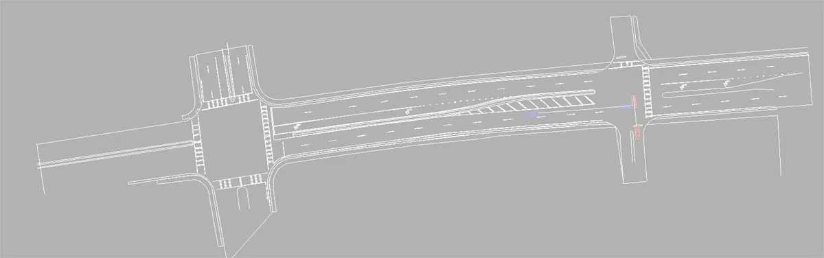
In Virtual CRASH you can create complex road geometries using the plane object. In this post, we will create a highway interchange ramp.
In this latest installment, we continue with our exploration of the Research Input for Computer Simulation of Automobile Collisions (RICSAC) test series. These tests make excellent benchmarks with which to study just how quickly and accurately Virtual CRASH can reproduce accident cases.
In the User's Guide writeup on RICSAC 1 (VC5 | VC4 | VC3), you are walked through the workflow of a typical accident reconstruction analysis involving a t-bone style impact based on a staged collision test from the Research Input for Computer Simulation of Automobile Collisions (RICSAC) series. In that case, using knowledge of the pre-impact orientations and post-impact rest positions and orientations, as well as the post-impact trajectories, we were able to iteratively converge on a reasonable solution for the collision, obtaining estimates of the pre-impact speeds. In this post, we will repeat this same process for the second RICSAC collision ("RICSAC 2").
In this blog post, we will discuss how to create custom sky modifications. In particular, we will focus on creating (1) an all-white sky and environment, (2) an all-black sky, and (3) a sky with stationary cloud effects.
In this post, we outline the simplified process for importing Virtual CRASH data into FARO HD and Reality.